Analysis of Cascading Outages from a Transient Stability Perspective – Potential Cascading Modes-Transient Stability (PCMTS)
PCMTS, fully integrated into POM Suite, analyzes of cascading outages while considering transient stability phenomenon and while modeling the protection system.
PCMTS, which is based on time domain simulation, addresses the following aspects of assessment of cascading outages:
- Identifies initiating events – three-phase and unbalanced faults;
- Considers generator out-of-step conditions, overloads and transient voltage deviation;
- Incorporates protection system modeling; and
- Quantifies the spread of the cascading outages.
Initiating events
PCMTS analyzes three-phase and unbalanced faults as initiating events. An event is classified as a cascading outage in PCMTS if it causes at least one of the following consequences:
- Sharp drop in transient voltages in a large part of the network
- Sharp drop in frequency followed by system separation
- Islands are formed as a result of protection operation, with significant amount of load/generation within the island
- Disconnection of large amount of generation
- Disconnection of large amount of load
For each initiating event, PCMTS determines the following information:
- Tripped elements, time of tripping and reason of tripping
- Amount of load/generation tripped as a result of relay operation
- Amount of load/generation that is isolated as a result of tripping a line/transformer
- Reason for a cascade being critical, if identified
- The value of maximum generator angle deviation in degrees
- Result of steady-state stability computation
PCMTS also performs additional checks:
- Generator angle deviation
Checks maximum change in the rotor angle deviation
- Steady-state stability
After time-domain computation is completed, all elements tripped as a result of a cascading chain, are tripped using steady-state (e.g., load flow) computation
Simulation of cascading events
Tripping occurs during a cascading event if at least one of the tripping criteria is met:
- Line tripping threshold
- Transformer tripping threshold
- Load tripping threshold
- Generator tripping thresholds
When one of the tripping criteria is satisfied, the corresponding element is being tripped. However, tripping occurs only if a criterion continues to be met during a time interval specified in the relay delay section. In this case, the element will be tripped after the time listed in the relay delay section has elapsed.
Relay operation is modeled using delays listed in the relay delays section. It is assumed that the above relays are installed on all lines, transformers, loads, and generators.PCMTS models the operation of the following types of relays during a simulation of cascading outages:
- Distance relays
- Over-current relays
- Under-voltage relays
- Under-frequency relays
Relay delays are user-defined.
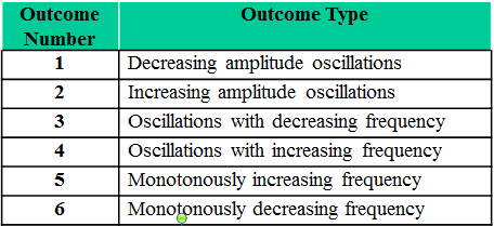
Possible outcomes of cascading events
PCMTS also identifies possible outcomes of cascading based on a determination and comparison of damping parameters.
Use of PCMTS at SPP
PCMTS is used for preventing the risk of uncontrolled outages and blackouts, and to dramatically improve IROL compliance.
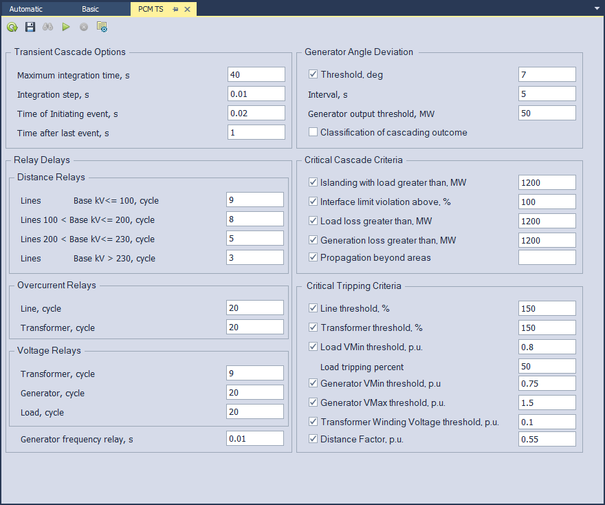
PCMTS settings at SPP:
- Distance relays are modeled to simulate using zone 1 protection of 55% of the line impedance for each transmission line:
- Delays for lines are as follows: <100kV (9cy); 100–200kV (8cy); 200-230kV(5cy);<230kV(3cy);
- Delays for transformers is 4cy.
- Over-current relays are modeled to simulate a 50% overcurrent with a 2000 MW maximum load loss.
- Under-voltage relays are modeled to simulate using a voltage threshold of 0.1 p.u. for transient voltage responses.
- Under-frequency relays are simulated using an angle threshold of 180 degrees for rotor angle changes.
- Gen angle – initial gen angle > angle threshold.
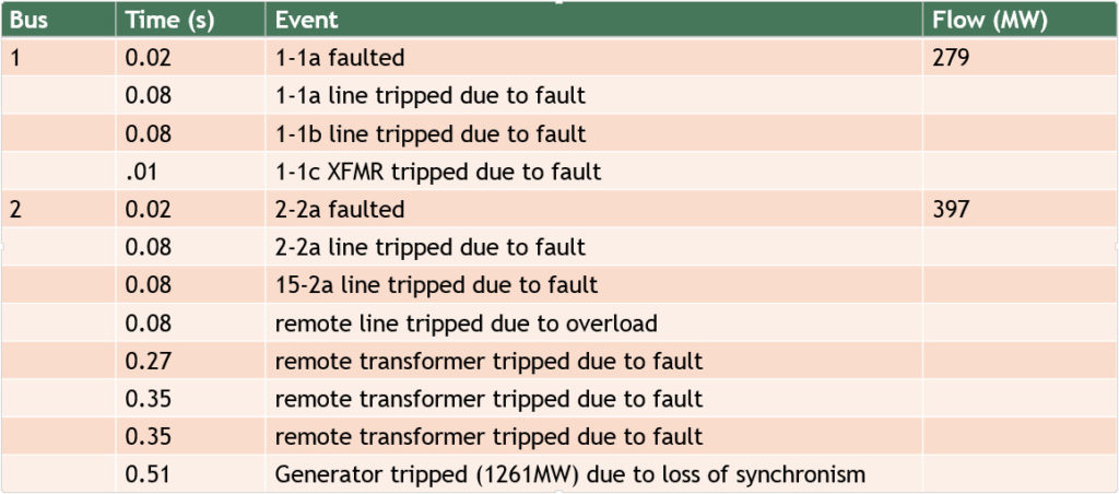
PCMTS results for P1 analysis at SPP, [1, 2] are shown in the figure below.
References
- D. Bowman, M.Y. Vaiman, M.M. Vaiman, “Cascading Outages Analysis from Transient Stability Perspective at SPP,” PACW Americas Conference 2016, Raleigh, North Carolina.
- 2017 IEEE PES General Meeting Tutorial: “Industry Best Practices, Needs, and Challenges in Cascading Analysis.”